This article is a little large for one post so I have split it into 2 parts. Here's part 1....
Ever since my 72 Corvette arrived I wanted to get the wiper door open and have a look inside the wiper well but the door was absolutely stuck - no amount of pulling, pushing or swearing would make it budge. Weeks of dousing the linkages and bushes in Plus Gas - usually a reliable help - had absolutely no effect. I definitely didn't want to force anything so decided to leave any further investigation until later in the restoration.
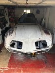
Roll the clock forward a year and the front end bodywork and the front and rear suspension are nearly done. In the picture below I have trial fitted the hood to make sure that the body and hood are reasonably well aligned - the gap that previously existed between the front edge of the hood and the bodywork has now gone.
Although it wasn't on the critical path for getting the car finished I thought that spending some time on the wiper mechanism would be a good antidote to some of the more heavy duty stuff I had been working on for the previous 6 months or so.
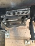
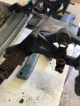
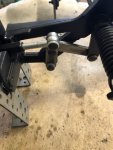
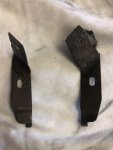
The wiper assembly is constructed of a cranked steel rod supported by three bushed aluminium brackets that locate the rod transversely across the body allowing the rod to rotate. The brackets are bolted to the bulkhead: one at each end of the rod and one towards the middle but offset to the passenger side. The two brackets at the ends of the rod locate a 5 bar link arrangement that when activated, move the attached wiper door upwards and outwards keeping the door parallel to the ground. There are two further linkages. One connects to the vacuum actuator that operates the wiper door and a second which when extended, trips a switch to provide an electrical signal when the wiper door has reached its upper limit. For additional support the left and right aluminium brackets are connected to two small steel brackets, one either side, that bolt to the birdcage just below the windscreen.
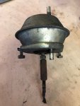
Back to my car .... the wiper door was still stuck and the only way I was going to get it open was to strip it down in situ by removing the grille, then wiper motor and washer tubes. After this was done the wipers and connecting links could be removed by undoing the 4 bolts connecting each wiper pivot to the bulkhead. The actuator mechanism rod had already rusted through but the actuator and bracket were removed anyway to give more space. The limit switch mechanism was also disconnected and removed.
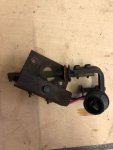
This gave enough room to get access to the bolts high up under the wiper door that keep the left and brackets in place. Once these bolts and the bulkhead bolts were undone the whole door and related mechanism could be removed as a unit from the car.
On the bench the wiper door was removed from the rest of the mechanism. Fortunately the four shoulder bolts came out quite easily even though only one bolt head was intact enough to put a socket on it - the other three had corroded requiring the remaining stubs to be filed down and removed with a set of Mole grips.
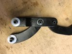
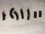
All the linkage rivets at each end of the cranked rod were drilled out so that the individual lever elements could be removed, cleaned, de-rusted and repainted. The plastic bushes in these links had hardened and most of them cracked or split on removal.
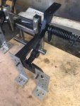
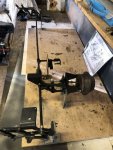
Even after all this, the bar would still not rotate in the brackets - it was still seized solid. Thus a jig was made using some joinery brackets from Wickes and a large piece of 3/4" plywood and the wiper door mechanism was mounted on this to mimic the way it is located in the car - the brackets taking the place of the Corvette bulkhead. In the picture below (taken towards the end of the rebuild) you will notice a photocopy of a page from the Factory Assembly Manual which provides really useful guidance on the restoration. I find it useful to copy a page and laminate it so that it can be wiped clean periodically and saves the FAM from getting messed up.
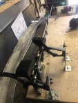
A separate jig was constructed so that I could hold the rod still, cut the rod between two fixed points with a cutting disc and then remove and renew the end bracket bushes. I started on the right hand side, refurbished the bracket, replaced the bush, then dressed the two ends of the rod and welded them back together. The left hand side bracket was done in the same way.
However these bushes, brackets and levers are not available individually - although the entire mechanism can be bought as a unit if required. I did some research and found some oil filled flanged bronze bushes and also some nylon bushes that could be used for the three supporting brackets where the rod passes through. I also found some bronze bushes that could replace the smaller linkage bushes but as the plastic stock ones are available I decided to buy these (from Corvette Kingdom) as these would be easier to fit.
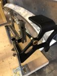
Either the bronze or nylon bushes could have been used - each bush type has its own pros and cons. Bronze: better mechanical fit but poor corrosion characteristics when employed with an aluminium casting that gets wet. These also required some fettling before they would fit correctly (a very small reduction in the outside diameter). Nylon: slightly inferior mechanical fit but otherwise very similar to the original items and corrosion resistant. I decided in the end to use the bronze bushes and just keep an eye on them periodically for any tell-tell signs of a corrosive reaction between the bronze and aluminium. Unfortunately the difficult-to-replace aluminium bracket will corrode in preference to the made-in-thousands bronze bush so it was an important consideration.
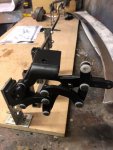
The bronze bushes can be bought in small numbers relatively cheaply from UK distributors. The only place I found the nylon bushes of the right size was from a wholesaler in Burnley so I had to buy a hundred..... Fortunately they are very cheap. If anyone wants some let me know!
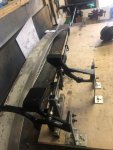
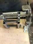
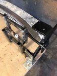
Both types of bushes can be seen below on the jig. A nylon bush has been installed and is being tested for fit.
continued in the next post........
Ever since my 72 Corvette arrived I wanted to get the wiper door open and have a look inside the wiper well but the door was absolutely stuck - no amount of pulling, pushing or swearing would make it budge. Weeks of dousing the linkages and bushes in Plus Gas - usually a reliable help - had absolutely no effect. I definitely didn't want to force anything so decided to leave any further investigation until later in the restoration.
Roll the clock forward a year and the front end bodywork and the front and rear suspension are nearly done. In the picture below I have trial fitted the hood to make sure that the body and hood are reasonably well aligned - the gap that previously existed between the front edge of the hood and the bodywork has now gone.

Although it wasn't on the critical path for getting the car finished I thought that spending some time on the wiper mechanism would be a good antidote to some of the more heavy duty stuff I had been working on for the previous 6 months or so.
The wiper assembly is constructed of a cranked steel rod supported by three bushed aluminium brackets that locate the rod transversely across the body allowing the rod to rotate. The brackets are bolted to the bulkhead: one at each end of the rod and one towards the middle but offset to the passenger side. The two brackets at the ends of the rod locate a 5 bar link arrangement that when activated, move the attached wiper door upwards and outwards keeping the door parallel to the ground. There are two further linkages. One connects to the vacuum actuator that operates the wiper door and a second which when extended, trips a switch to provide an electrical signal when the wiper door has reached its upper limit. For additional support the left and right aluminium brackets are connected to two small steel brackets, one either side, that bolt to the birdcage just below the windscreen.
Back to my car .... the wiper door was still stuck and the only way I was going to get it open was to strip it down in situ by removing the grille, then wiper motor and washer tubes. After this was done the wipers and connecting links could be removed by undoing the 4 bolts connecting each wiper pivot to the bulkhead. The actuator mechanism rod had already rusted through but the actuator and bracket were removed anyway to give more space. The limit switch mechanism was also disconnected and removed.


This gave enough room to get access to the bolts high up under the wiper door that keep the left and brackets in place. Once these bolts and the bulkhead bolts were undone the whole door and related mechanism could be removed as a unit from the car.
On the bench the wiper door was removed from the rest of the mechanism. Fortunately the four shoulder bolts came out quite easily even though only one bolt head was intact enough to put a socket on it - the other three had corroded requiring the remaining stubs to be filed down and removed with a set of Mole grips.
All the linkage rivets at each end of the cranked rod were drilled out so that the individual lever elements could be removed, cleaned, de-rusted and repainted. The plastic bushes in these links had hardened and most of them cracked or split on removal.

Even after all this, the bar would still not rotate in the brackets - it was still seized solid. Thus a jig was made using some joinery brackets from Wickes and a large piece of 3/4" plywood and the wiper door mechanism was mounted on this to mimic the way it is located in the car - the brackets taking the place of the Corvette bulkhead. In the picture below (taken towards the end of the rebuild) you will notice a photocopy of a page from the Factory Assembly Manual which provides really useful guidance on the restoration. I find it useful to copy a page and laminate it so that it can be wiped clean periodically and saves the FAM from getting messed up.

A separate jig was constructed so that I could hold the rod still, cut the rod between two fixed points with a cutting disc and then remove and renew the end bracket bushes. I started on the right hand side, refurbished the bracket, replaced the bush, then dressed the two ends of the rod and welded them back together. The left hand side bracket was done in the same way.

However these bushes, brackets and levers are not available individually - although the entire mechanism can be bought as a unit if required. I did some research and found some oil filled flanged bronze bushes and also some nylon bushes that could be used for the three supporting brackets where the rod passes through. I also found some bronze bushes that could replace the smaller linkage bushes but as the plastic stock ones are available I decided to buy these (from Corvette Kingdom) as these would be easier to fit.

Either the bronze or nylon bushes could have been used - each bush type has its own pros and cons. Bronze: better mechanical fit but poor corrosion characteristics when employed with an aluminium casting that gets wet. These also required some fettling before they would fit correctly (a very small reduction in the outside diameter). Nylon: slightly inferior mechanical fit but otherwise very similar to the original items and corrosion resistant. I decided in the end to use the bronze bushes and just keep an eye on them periodically for any tell-tell signs of a corrosive reaction between the bronze and aluminium. Unfortunately the difficult-to-replace aluminium bracket will corrode in preference to the made-in-thousands bronze bush so it was an important consideration.

The bronze bushes can be bought in small numbers relatively cheaply from UK distributors. The only place I found the nylon bushes of the right size was from a wholesaler in Burnley so I had to buy a hundred..... Fortunately they are very cheap. If anyone wants some let me know!
Both types of bushes can be seen below on the jig. A nylon bush has been installed and is being tested for fit.

continued in the next post........


