Innovate DLG-1 can be google’d for detailed system information.
I used ‘no weld’ bungs from AEM to locate the sensors about midway back. Also worth investing in plugs to stopper the sensor holes when the need arises.
The system has about 11’ of cable to connect between sensor and gauge in 3 pieces with connectors.
One sensor connects to the gauge directly and the other connects to a black box that then connects to the same gauge. The gauge and black box are separately powered by a fused 12v keyed wire, and are both earthed.
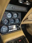
I mounted the gauge near the other instruments.
There is a start up sequence to get the electronics to communicate, followed by a sensor calibration in air, before fitting the sensors into the exhaust.
I connected my laptop for data logging with the lead supplied but I needed a ‘serial to usb’ connector from Amazon.
Software is downloaded from Innovate for gauge setup, not required, and logging.
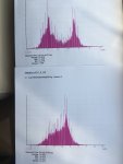
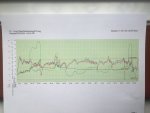
I ran the car for about 40 minutes of varied driving. Car ran well. The software allows some statistical output as well as the double afr versus time track. This first run produced good correlation between the sensors but a surprising ‘twin peak’ for the afr readings. The average afr was 13. Stoich is 14.7, so perhaps a bit rich.
For the second run out I adjusted the Holley idle screws. These were not equal as they should be with one set richer than the other. I used a vacuum gauge and also the afr gauge to set these equal and leaner. The car ran just as well.
The afr statistics for this run, same journey, gave an average afr of 14 and a single peak with a range of afr peaking at 14.7.
For the next runs I want to better correlate periods of cruising, accelerating and WOT with the trace. The software allows selection of parts of the record for the statistical analysis which would allow comparison of the afr for these phases with published wisdom for best afr for each type of driving.
A single sensor system would be cheaper and quicker to install and probably as useful. The only benefit perhaps of the dual system would be an indication of exhaust leak or mis firing, etc, on one side, or time to recalibrate the sensors.