Current Draw

TimP

CCCUK Member
Does anybody happen to know what the typical current draw is on the battery when the ignition key is turned to 'accessories'? (assuming that none of the optional accessories like lights and wipers etc are switched off). I'm thinking that this should just be the ignition circuit and any warning lights that come on with the key (handbrake on etc..)

This is for a 72 T-Top.

I am (still) in the process of testing the wiring prior to starting the engine and it's not right at the moment. It seemed to be ok and now I seem to have a short somewhere. Part of the problem is I don't know what good looks like.
 

Mr. Cricket

Committee Member
Does anybody happen to know what the typical current draw is on the battery when the ignition key is turned to 'accessories'? (assuming that none of the optional accessories like lights and wipers etc are switched off). I'm thinking that this should just be the ignition circuit and any warning lights that come on with the key (handbrake on etc..)

This is for a 72 T-Top.

I am (still) in the process of testing the wiring prior to starting the engine and it's not right at the moment. It seemed to be ok and now I seem to have a short somewhere. Part of the problem is I don't know what good looks like.
I can test my '71 shortly. Small block LT-1 so it should be comparable to your set up?

And I take it you want everything off as your statement above is misleading
 

TimP

CCCUK Member
Many thanks - that's really good to know. Mine is drawing about 4amps at the moment, with everything supposedly off, which is way too high - must have a bad connection or wiring fault somewhere.

Once again, many thanks.
 

Grahamred70

CCCUK Member
Try removing fuses one by one and watch for any change, in accesory position only feed live should be the radio I think but certainly not the ignition and warning light circuit, did you measure the draw with the ignition key turned off? Should be minimal if not alternator is a possible cause.

Graham
 

Mad4slalom

Well-known user
Does anybody happen to know what the typical current draw is on the battery when the ignition key is turned to 'accessories'? (assuming that none of the optional accessories like lights and wipers etc are switched off). I'm thinking that this should just be the ignition circuit and any warning lights that come on with the key (handbrake on etc..)

This is for a 72 T-Top.

I am (still) in the process of testing the wiring prior to starting the engine and it's not right at the moment. It seemed to be ok and now I seem to have a short somewhere. Part of the problem is I don't know what good looks like.
No help on the leccy stuff but a heads up , I had owned my 72 a while when one day realised I had no dash lights on turning key and thought I had a problem . Turns out there is no charging light as in modern cars so I think it was only door ajar and Park brake lights otherwise nothing which I think is normal. I disconnected my seat belt switches when fitting the retro lap and shoulder belts. 👍
 

TimP

CCCUK Member
Try removing fuses one by one and watch for any change, in accesory position only feed live should be the radio I think but certainly not the ignition and warning light circuit, did you measure the draw with the ignition key turned off? Should be minimal if not alternator is a possible cause.

Graham
Hi Graham, thanks for your post. This is a really good suggestion and will be trying this over the next week or so. However it won't be the first time that I will be wishing that they had put the fusebox in a more accessible place! :rolleyes:

I think I have might been thinking about the wrong position when I quoted 'Accessory' - there are more positions on the ignition that I had thought so I'm going to come back to this when I have got a better understanding of the ignition positions and associated wiring. I will also take some current readings from all positions and with different circuits for reference.

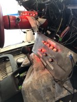
In the meantime I'm glad to report that the indicators, dash lights, park brake, h/l pod open warnings are all working. The HL Main Beam idiot light is proving elusive at the moment but it's a good excuse to find out a lot more about how the lamps/front loom works - more on this in a later post. Finding that it is really difficult to test, inspect, probe and resolve issues with the dash and the centre instrument console in place I created an additional false panel (I had made/used one earlier for the speedo/rev counter lights) so that I can troubleshoot much more easily....
Electrical 11.jpg
I'm also experimenting with different suppliers/designs of LED bulbs at the same time. There's quite a lot of variety in quality and brightness.
 

TimP

CCCUK Member
No help on the leccy stuff but a heads up , I had owned my 72 a while when one day realised I had no dash lights on turning key and thought I had a problem . Turns out there is no charging light as in modern cars so I think it was only door ajar and Park brake lights otherwise nothing which I think is normal. I disconnected my seat belt switches when fitting the retro lap and shoulder belts. 👍
On my car, dash illumination lights only come on when the headlight switch is pulled out - hope that's correct. I haven't got to the seat belt circuits operating yet - they seem to be unnecessarily complex for such a simple thing so I may end up disabling them too, if only for now so that I can focus on getting the engine started.

The park brake is definitely working but I haven't tried the door ajar light circuit as the switches aren't fitted yet .....
 

Grahamred70

CCCUK Member
Hi Tim, do you have the wiring diagram for your car I think they are on the forum for download if I remember correctly?
Graham
 

Grahamred70

CCCUK Member
I'm also experimenting with different suppliers/designs of LED bulbs at the same time. There's quite a lot of variety in quality and brightness.

Hi Tim, another tip re dash lights, I fitted leds to my dash only to find when I'd struggled to get it all back together I had no dash lights, still don't actually, but I can only assume the dash lights are connected opposite to convention i.e. the case is positive and the button on the bottom is negative when installed?

Graham
 

TimP

CCCUK Member
Hi Tim, do you have the wiring diagram for your car I think they are on the forum for download if I remember correctly?
Graham
Hi Graham,
Yes - I do have the large A2 laminated wiring diagram which I have pinned on the wall in my garage. Some of the printing is a bit blurred but I also have the 72 service manual which has the originals if I need detail. The reason for producing the quick ref guide was because I was continually finger tracing on the wiring diagram - it was much quicker in the end to put on paper 'a destination diagram' to show where every wire was going to rather than just what colour it was. After doing this wire colour matching and continuity checking was really quick. As an added benefit having put the work into producing it I now feel that I understand the wiring layout which is helpful when troubleshooting.
 

TimP

CCCUK Member
I'm also experimenting with different suppliers/designs of LED bulbs at the same time. There's quite a lot of variety in quality and brightness.

Hi Tim, another tip re dash lights, I fitted leds to my dash only to find when I'd struggled to get it all back together I had no dash lights, still don't actually, but I can only assume the dash lights are connected opposite to convention i.e. the case is positive and the button on the bottom is negative when installed?

Graham
The LEDs I am using all have a negative (ie -12v) case and a positive tip. Being LEDs they won't work the other way around. One thing I have done to ease removal and installation of the dash is to produce a dash light loom and just feed a common point from one of the grey wires in the loom rather than feed each the 5 or 6 wires to each of the bulbs. Installed this way they work just fine in my car. They are dependent on a good earth on both the speedo/rev panel and the centre gauges. I painted the back of my gauges as they were corroded so I had to scrape off the surrounds of the holes to ensure that there was a connection between the gauge casing and the bulb holder periphery.

The LEDs I have experimented with are from two main sources: Cheap direct from China eBay items that tend to be a bit dim, not very well made and are slightly off on dimensions, so that they fall out of the bulb holders when installing the dash - which is really annoying.

The ones I have tried from www.classiccarleds.com are far superior if more expensive but well worth it as they are clearly better quality, brighter and stay put in the holder.

Also it seems that different colours have different intensities so green LEDs consuming the same current appear brighter than red or blue ones, to my eyesight anyway.
 

TimP

CCCUK Member
Hi Graham,
Yes - I do have the large A2 laminated wiring diagram which I have pinned on the wall in my garage. Some of the printing is a bit blurred but I also have the 72 service manual which has the originals if I need detail. The reason for producing the quick ref guide was because I was continually finger tracing on the wiring diagram - it was much quicker in the end to put on paper 'a destination diagram' to show where every wire was going to rather than just what colour it was. After doing this wire colour matching and continuity checking was really quick. As an added benefit having put the work into producing it I now feel that I understand the wiring layout which is helpful when troubleshooting.
I should also have mentioned that on the engine loom on my 72 there was at least one difference between the wiring one my car and the wiring the diagram. The 'R' feed (think I got that right) from the starter should be a yellow wire that goes to the coil +ve to boost the spark when starting but my car loom - and it does look factory - was red. This had fooled the previous owner (and the dealer who sold it) and they had connected it to the windscreen wiper motor which also has a red cable. I re- installed the old loom as it had been originally but when that didn't make sense it became clear that there was a discrepancy. I have now replaced the old loom with a brand new LectricLimited one which matches the wiring diagram. It's really nicely made too although I will have to add the white wire that goes to the hood open switch (which won't be difficult) that was in my original engine loom but isn't in the new one. Not sure if it is supposed to be in the engine loom but it was certainly wrapped in with it originally.
 

teamzr1

Supporting vendor
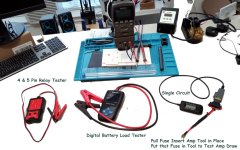
If some circuit is drawing the battery voltage down, there are simple tools to determine which circuit/function is the problem

Tester on right tests 4 or 5 pin relays to assure the coil of the relay works, and tests that the relay is changing states

Tool in the middle tests the battery when connect to vehicle and when connected and also does load testing to assure no weak or bad cells

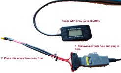
Tool on right, pull any fuse and put it into the tool and then plug the tool into the fuse panel to replace the fuse
This measures the AMP draw of that fused circuit and would tell than if whatever is feed by that circuit is correctly not drawing or
is drawing current when it should not be

All 3 tools are fairly cheap in costs

circuitamptester.jpg

AMPtesters.jpg
 

TimP

CCCUK Member
If some circuit is drawing the battery voltage down, there are simple tools to determine which circuit/function is the problem

Tester on right tests 4 or 5 pin relays to assure the coil of the relay works, and tests that the relay is changing states

Tool in the middle tests the battery when connect to vehicle and when connected and also does load testing to assure no weak or bad cells

Tool on right, pull any fuse and put it into the tool and then plug the tool into the fuse panel to replace the fuse
This measures the AMP draw of that fused circuit and would tell than if whatever is feed by that circuit is correctly not drawing or
is drawing current when it should not be

All 3 tools are fairly cheap in costs
Interesting. I have been 'testing' relays by opening them up and having a good look inside - a tool like this would be a whole lot easier, and pretty cheap to buy too. The fuse replacement current tester would be most useful to me right now and I shall investigate further. Thanks for suggesting these.
 

teamzr1

Supporting vendor
Here is an example of a 4 and 5 pin relay tester


This one has its own battery so portable


Here is current amp tool

Used one $13

New one, just 1 left $30


Here is a steal, a new one just $10


Grahamred70

CCCUK Member
I should also have mentioned that on the engine loom on my 72 there was at least one difference between the wiring one my car and the wiring the diagram. The 'R' feed (think I got that right) from the starter should be a yellow wire that goes to the coil +ve to boost the spark when starting but my car loom - and it does look factory - was red. This had fooled the previous owner (and the dealer who sold it) and they had connected it to the windscreen wiper motor which also has a red cable. I re- installed the old loom as it had been originally but when that didn't make sense it became clear that there was a discrepancy. I have now replaced the old loom with a brand new LectricLimited one which matches the wiring diagram. It's really nicely made too although I will have to add the white wire that goes to the hood open switch (which won't be difficult) that was in my original engine loom but isn't in the new one. Not sure if it is supposed to be in the engine loom but it was certainly wrapped in with it originally.
That's a bit misleading as red wires are normally permanent live which would be fun as your engine would never stop!! Can only think a PO had replaced the wire at some time and only had some red cable to hand.

Graham
 
Top