antijam
CCCUK Member
...and the case of my C3 they currently (pun intended) seem to be electrical. First the clock stopped, then the battery isolator isolated at the wrong time, now I've just noticed that the ammeter has ceased to function. I'm not sure quite when this first happened - I don't normally give the ammeter much attention. I guess it could be a side effect of my fiddling about to sort out the first two problems. Whatever the cause, it needs sorting. Before accessing the meter I did check that the alternator was actually charging, which it is, but with no deflection of the meter. Putting the lights on and sounding the horn produces no negative deflection either.
So, it's off with the passenger side lower dash panel (again!) which gives me access to the back of the ammeter. The meter is wired with a two-pole connector, one wire being black, the other black/white. I remove the connector and check continuity between the two spade terminals on the meter. It's open circuit so the meter is duff. While I'm there I check voltage at the plug; there's 12V on the black lead but 0V on the black white. There should be almost identical voltage, at around 12V on both, so something else is wrong too.
The ammeter wiring circuit is shown by this diagram...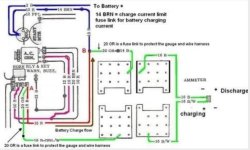
The supplies to the ammeter are protected by fusible links. Since I'm seeing 12V on the 'B' wire that part of the circuit must be sound. Since there's no voltage on the 'B/W' wire I'm inferring that the fusible link in that part of the circuit has failed. The diagram indicates that the fusible link is situated in the wiring between the bulkhead connector and the horn relay connections. I don't know what the fusible link looks like and so far checking the wiring in the engine bay has not shown anything obvious. I'm wondering if I'm looking for just a single length of wire or whether the link is actually some sort of module perhaps? Can anyone help me identify it and if so, how is it replaced?
I have a new meter coming from the States but in the meantime everything else in the car seems to work so I'll carry on driving until it arrives. To replace the ammeter the whole centre instrument cluster has to come out (yet again!) and that's not a job i'm looking forward to, but before attempting the replacement I do need to sort out the supply to the meter.
(Would'nt be any fun if it was easy, would it?)

So, it's off with the passenger side lower dash panel (again!) which gives me access to the back of the ammeter. The meter is wired with a two-pole connector, one wire being black, the other black/white. I remove the connector and check continuity between the two spade terminals on the meter. It's open circuit so the meter is duff. While I'm there I check voltage at the plug; there's 12V on the black lead but 0V on the black white. There should be almost identical voltage, at around 12V on both, so something else is wrong too.
The ammeter wiring circuit is shown by this diagram...

The supplies to the ammeter are protected by fusible links. Since I'm seeing 12V on the 'B' wire that part of the circuit must be sound. Since there's no voltage on the 'B/W' wire I'm inferring that the fusible link in that part of the circuit has failed. The diagram indicates that the fusible link is situated in the wiring between the bulkhead connector and the horn relay connections. I don't know what the fusible link looks like and so far checking the wiring in the engine bay has not shown anything obvious. I'm wondering if I'm looking for just a single length of wire or whether the link is actually some sort of module perhaps? Can anyone help me identify it and if so, how is it replaced?
I have a new meter coming from the States but in the meantime everything else in the car seems to work so I'll carry on driving until it arrives. To replace the ammeter the whole centre instrument cluster has to come out (yet again!) and that's not a job i'm looking forward to, but before attempting the replacement I do need to sort out the supply to the meter.
(Would'nt be any fun if it was easy, would it?)


