C5 1999 Model ABS and Traction Lights came ON yesterday - HELP

teamzr1

Supporting vendor
So you know that 2.73 rearend gear is not going to be ramping up RPM and MPHs as other sports cars

Second is the A4 is set up to drive like a Caddy since mostly waxers ( and women :) drive them
GM sets up the way the A4 reacts and shifts to be smooth and the suspension to be softer

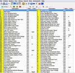
Attached below is a file you can download
What I did is take a C5 with A4 and what you see is all the GM settings on how it commands the auto shifting
It is set up to slower shift times, reacts slower and is frankly calibrated for the waxers, so it drives nice
but has no balls when you get on it

Those with A4s and want to do some grassroots racing like an autocross will swap out that 2.73 gear to the MN6 rear gear of 3.42
Further, wanting more come to me and I redo all those setting I show you in the PCM so that it shifts quickly less latency
allows more torque, carries each gear to higher RPMs and MPH and downshifts much quicker

Take some time and look at the stock A4 setting in the text file attached
 

Attachments

  • mark shipley 03.txt
    34.1 KB · Views: 2

teamzr1

Supporting vendor
Now as suspension
As you see when launching the front comes up, ass end squats which then shifts the weight back and onto the rear tires for better traction
which is good, esp at drag strip or racing some broad at a stoplight :)
Now what a driver may like is to control understeer or maybe setup for oversteer and that is by changing if and how much body roll

Here is a list I made many years ago about how to make the changes wanted :

Adjusting for Over or Understeer Conditions​

  • Make the following adjustments to correct for either oversteer or understeer
  • Different corrections can get the same results
Add type of shocks, lowering vehicle, leak or coil spring rates

Correct OversteerAdjustmentsCorrect Understeer
HigherFront Tire PressureLower
LowerRear Tire PressureHigher
SmallerFront Tire SectionLarger
LargerRear Tire SectionSmaller
More PositiveFront Wheel CamberMore Negative
More NegativeRear Wheel CamberMore Positive
Toward Toe-InFront Wheel ToeToward Toe-Out
Toward Toe-OutRear Wheel ToeToward Toe-In
More NegativeFront Wheel CasterMore Negative
StiffenFront SpringsSoften
SoftenRear SpringsStiffen
Stiffen (Thicken)Front Sway BarSoften (Thinner)
Soften (Thinner)Rear Sway BarStiffen (Thicker)
More ForwardWeight DistributionMore Rearward

In the end you can wake that A4 5 with engine/tranny tune, could replace read end gear for lower one, type of wheel alignment,
type of wheel/tires used and deciding on replacing leaf springs with coilover with shocks and the spring rate of coils
Over / understreer by thickness of front/rear sway bars
 

Nickerbocker Glory

CCCUK Member
Thanks JR - interesting info... but the rear end gear ratio on my C5 is a G90 Performance 3.15 - so I imagine the performance figures won't be so dire compared to the manual car. And while I won't be taking the car to track days or up to 160 mph, I'm not a pizza munching waxer either :) I'd just like to have a tractable responsive car with good acceleration and roadholding.. Which I don't have at the moment.
 

Nickerbocker Glory

CCCUK Member
I'm used to cars that are stickier under hard acceleration so the ride is virtually flat and the steering isn't lighter (although the XKR steering is light anyway its consistent, And I won't be fitting coil-overs or lowering the car (we have a pothole problem here in UK). As for racing broads at the lights (lol) at 73 they laugh at me... I do my speed driving mostly on empty roads on the continent. Here in the UK we have more cars per mile of road than most other countries - and speed cameras!
 

teamzr1

Supporting vendor
Yes the 3.15 gear will help, but the problem still is the A4 is tuned to be lazy, same tune for both rear end A4 gears

The car will wake up with a good engine and A4 tune
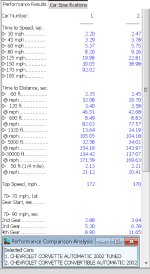
As example, I took a stock C5 A4 with the 3.15 and then took another stock C5 A4 with same 3.15 but had tuned the engine and A4 for performance C5 owner wanted

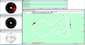
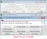
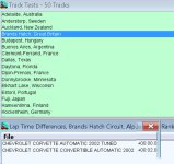
As you see with the tune the engine gains about 40 HP and 25 ft/lbs torque and all the others changes I made for engine and woke the A4 up

tunerace.jpgtunecmpmph.jpgtunecmpc.jpgtuneca.jpgcmpt.jpg
 

Nickerbocker Glory

CCCUK Member
Hi JR

Autocar tested a '97 auto in Germany.
It achieved 0-60 in 5.7 secs and 0-100 in 13.1 secs with the standing quarter coming up in 14.1 @ 104mph. These of course were electronically timed and independent of the car's speedometer. (One very important factor was the Performance Axle with the final drive ratio of 3.15:1.) Which endorses precisely the data you have set out in your latest posting.

I must reflect on how best to proceed - in pursuit of a much improved 'stock' C5, do I go face to face with an established UK performance engineering re-map, or a vastly experienced but remote (in both senses of the word) Stateside resource. For the former I have a strong personal endorsement by another established Club member. In your case I am attracted to both the ease of operation (no travel) and the bonus of a subsequent tweak / fine tune once I have familiarised myself with the new re-mapped set-up.

Once again - your attention to detail much appreciated. Gracie mille - I'll keep you posted.
 

Nickerbocker Glory

CCCUK Member
Hello JR, Petchy 56, Stingray et al...

Sadly I'm still grappling with intermittent ABS + Traction Control lights / issues.
I cleaned all the connectors and grounds as suggested.
Cleared the Codes.
All good for a couple of days so had Borla Exhaust, Competition Sway Bars and Bilstein Shocks -
Prior to engaging with a TeamZR1 Remote Tune Up.
(Obviously - sadly - premature: yeah, always impatient to get things done).

Then the lights came back on: DIC Code C1255 + others but all H / Historic as in 'intermittent')
Change my Battery for an AGM Optima putting out 1000 instead of the 700 on the (Brit) Varta.
Clear the Codes again.

Start up / run engine for gentle warm up - within a few minutes both lights back on.

I run the DIC:
10 - PCM P1571 HC. ASR Desired Torque
28 - TCS NO COMM (Previously - always - C1255 'the kiss of death' never the more common C1214)

40 - BCM No Codes
58 - SDM U1040 HC. Loss of Communication with TCS
60 - IPC U1040 H. Loss of Communication with TCS

99 - HVAC No Codes
HU - LDCM No Codes
HI - RDCM No Codes
H6 - SCM No Codes
BU - RFA No Codes

I wonder how best to proceed.....
I have been quoted the following for a replacement module by Dino at CorvetteSalvage.com
Nick,
We would need to know if it’s a M or V on the white sticker of the module or supply us with your VIN. The non active (M) brake pump assembly is $1850 and the active (V) brake pump assembly is $2350.​
But given this is for a 30k mile exquisitely maintained 2 previous owners C5 in (otherwise) excellent condition I still think there must be a way to get this sorted without resorting to a secondhand part of unknown mileage and (I imagine) very short term warranty.

I read somewhere that the EBCM Module pre 2000 comes with two tiers / platforms of electronics. The top (Power) is accessible and repairable
The bottom sunk in silicone unrepairable. Do I send the module off to see if the fault is (wouldn't that be wonderful) on the top tier and repairable?

Its all a bit of a head-f***.
Suggestions welcome - thanks - Nick
 

teamzr1

Supporting vendor
Hello JR, Petchy 56, Stingray et al...

Sadly I'm still grappling with intermittent ABS + Traction Control lights / issues.
I cleaned all the connectors and grounds as suggested.
Cleared the Codes.
All good for a couple of days so had Borla Exhaust, Competition Sway Bars and Bilstein Shocks -
Prior to engaging with a TeamZR1 Remote Tune Up.
(Obviously - sadly - premature: yeah, always impatient to get things done).

Then the lights came back on: DIC Code C1255 + others but all H / Historic as in 'intermittent')
Change my Battery for an AGM Optima putting out 1000 instead of the 700 on the (Brit) Varta.
Clear the Codes again.

Start up / run engine for gentle warm up - within a few minutes both lights back on.

I run the DIC:
10 - PCM P1571 HC. ASR Desired Torque
28 - TCS NO COMM (Previously - always - C1255 'the kiss of death' never the more common C1214)

40 - BCM No Codes
58 - SDM U1040 HC. Loss of Communication with TCS
60 - IPC U1040 H. Loss of Communication with TCS

99 - HVAC No Codes
HU - LDCM No Codes
HI - RDCM No Codes
H6 - SCM No Codes
BU - RFA No Codes

I wonder how best to proceed.....
I have been quoted the following for a replacement module by Dino at CorvetteSalvage.com

But given this is for a 30k mile exquisitely maintained 2 previous owners C5 in (otherwise) excellent condition I still think there must be a way to get this sorted without resorting to a secondhand part of unknown mileage and (I imagine) very short term warranty.

I read somewhere that the EBCM Module pre 2000 comes with two tiers / platforms of electronics. The top (Power) is accessible and repairable
The bottom sunk in silicone unrepairable. Do I send the module off to see if the fault is (wouldn't that be wonderful) on the top tier and repairable?

Its all a bit of a head-f***.
Suggestions welcome - thanks - Nick

Being you state this is intermittent, I would think if some electronics in the EBCM was faulty that the failure would be all the time

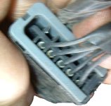
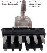
You say you checked all the wiring, did you take apart the ground splice packs ( on the frame below the headlights) that look like this )
it bolts to the frame and you have to pry it apart

splicepack2.jpg

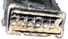
to see it look bad like this, so you can see from the outside the pack looks fine but inside a fricking mess
This is the female spade connectors

splicebad.jpg

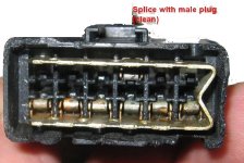
After cleaned up looks like this
splice_4.jpg

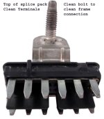
This is the top male pins after cleanup
splicpackclean.jpg

The fact you're getting the U comm DTCs still sounds like the EBCM is not talking on the Starbus network, and if so then false DTCs would trip

Another claim of the C1255 is really an ign switch problem where the voltage connection is flaky causing an intermittent voltage to controllers like the EBCM

There could be a solenoid of EBCM for one of the wheels for ABS sticking, maybe worth finding some road and make some hard
turns or movements to force ABS to kick on/off multi times

That vendor has to be F'ing nuts to ask almost $2,000 for that small controller, total screwover :(
 
Last edited:

Nickerbocker Glory

CCCUK Member
Thanks JR

I have tried the hard turns / movements and braking.... to no avail.
Why has the TCS intermittent HISTORIC gone to NO COMM?
Does that indicate the EBCM Module is completely shot or that there's a loose connection somewhere?
Do you (or anyone else) have a reliable source for a secondhand 1999 EBCM if it does turn out to be shot ?
I guess having mine removed from the car and tested is the next step).?
Do I recall you saying you had a later (repairable?) module in your 1999 C5?
So many wearying questions -
For you and for me....

Why on earth did I chop in a fully sorted no-problems faster XKR for a Corvette?
Nostalgia maybe - first captivated in 1966 during a short drive with Sheik Esa across the desert. And 30 years later driving my 66 427 around Paris (where I lived) and down to St Tropez and Barcelona. As well as - let's face it - The XKR is just a sanitised aluminium tea tray that pulls you up to 100mph in 12 seconds with a minimum of fuss and exhilaration.....

Just another Corvette story of heart ruling head... :)
Perseverance required - as well as deep pockets it would seem.
Disheartened but pressing on.
 

teamzr1

Supporting vendor
It is very hard to solve problems like this when using a decent OBD-II scanner would pinpoint the problem within a few minutes as
the scanner captures all functions, and good/bad data at the same time to then analyze
In most cases, ALL U (comm) codes is a problem with wiring or their connection pins
Really is needed is the wiring schematic from the EBCM to the Starbus network next to the BCM located under the floor hatch on passenger floor

As I mentioned in another reply that if the EBCM losing connection to the cars network (Starbus) then of course it cannot send the data to controllers like the BCM or PCM and thus the controllers cannot correctly respond and control

Next to the BCM is the Starbus network wires, and the controllers connect to it.
You need to be sure ALL the connectors there are clean and tight and if need be using a meter from the wiring connector of EBCM to
the Starbus connector that the network wires are good from EBCM and Starbus network
There are some flat test connectors in that network, make sure they also are clean and fully connected

Yes, I replaced a relay in the EBCM of my 1999 C5 to solve a problem
Also, another club member here few months back did the same relay change.

swpsebcm.jpg
 

Nickerbocker Glory

CCCUK Member
Hey JR
You're wonderful - thanks 🙃
It's late here and I must spend some time with my wife instead of on my car...
As always your assessment accurate, your advice pinpoint and your help so appreciated...
I'll get back to you - Thanks - n
 

teamzr1

Supporting vendor
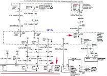
Please make sure you make use of these as I had to take photos of the GM C5 paper service manual and the print on back side
bleeds through, so I had to clean that all up
Here is the SWPS

C5EBTCMswps.jpg
 

teamzr1

Supporting vendor
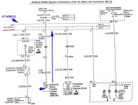
As I mentioned, all controllers have a data serial line to the Starbus network which is by the BCM
Now you know exactly what pins of that sensor, what color the wires are, and you see on Starbus connector one by BCM
exactly what serial wire of SWPS connects to the Starbus connector

So with the 2 pages you can ring out each wire of the SWPS and the Strabus data line from the EBTCM to the network
Again if the controller does not talk on the network then U DTCs trip

C5EBTCMswps2.jpg
 

Nickerbocker Glory

CCCUK Member
Superb JR - again big thanks... very clear and understandable. Most considerate of you to copy the service manual. I'll try to get on it with my mechanic friend Andy today. He always maintained that an intermittent fault suggested connection problems, not an internal issue with the module even though the C1255 code gets the Doomsday treatment on the Stateside forums. It certainly spooked me. With the wiring diagrams I'm confident the EBCM problem can be sorted now, which is a real relief.

I was thinking it might be helpful to have the option to communicate with you by phone - particularly as I intend taking you up on your offer to re-map the Vette remotely. I use WhatsApp which I read isn't popular / deemed a necessary App in the States (Why WhatsApp is So Unpopular in the USA). The advantage is you can call free all round the world if you phone when you're within reach of your broadband (i.e. phoning from office or home). We have a daughter working in Hong Kong and WhatsApp works really well... easy for you to install and its an all American App from Silicone Valley. Or maybe you prefer not spending time wandering round the houses on the mobile when your time could be better employed elsewhere. Just a thought.

Have a good day - obviously I'll let you know how I get on. ATB - Nick
 

Nickerbocker Glory

CCCUK Member
It IS the Splice Pack connector by the EBCM - two of the male connectors had virtually corroded away. My friend replaced the corroded male pins with the 'empty' pins and plugged it back together as a temporary measure while I order a couple of new connectors. It worked for a while but the intermittent fault is back of course, As you say ALL the Pins need to be connected - even the 'blank' test ones. Do you know where I can order the new connectors from in the USA? (Rock Auto don't talk / engage with queries they just request a part number). Really good to know its not the EBCM. Thanks - n
 

Nickerbocker Glory

CCCUK Member
I've located an American Parts supplier here who can obtain a Splice Pack Service Kit from USA (so correct replacement). Might it be worthwhile replacing any of the others - apart from the EBCM one - at the same time as a preventative measure? Or better to wait until a specific fault arises / shows on the DIC?
 

teamzr1

Supporting vendor
It IS the Splice Pack connector by the EBCM - two of the male connectors had virtually corroded away. My friend replaced the corroded male pins with the 'empty' pins and plugged it back together as a temporary measure while I order a couple of new connectors. It worked for a while but the intermittent fault is back of course, As you say ALL the Pins need to be connected - even the 'blank' test ones. Do you know where I can order the new connectors from in the USA? (Rock Auto don't talk / engage with queries they just request a part number). Really good to know its not the EBCM. Thanks - n

Did you take any photo of that ground splice pack when pried opened ?

Most people are not even aware of ground splice packs, and they are the biggest problem for odd random type of problems
In most cases the controllers are not controlling functions by the 12 and 5 volts but by reference to ground

As you see where the ground wires plug into the pack, there is enough space around the wires for water to get in and over time corrode the piss out of the male and female pins
I assume you mean the top with male pins, it is one large ground point so if rusted through so not all pins are going to ground then moving to a spare pin may not get to ground

splicpackclean.jpg

I suggest is buying some spare packs for future needs but also a good idea to force the packs open and check them, and if kind of looking OK is spray them with some type of waterproof lube like silicon and cover them with some plastic.
Maybe this vendor who sells all type of GM connectors has splice packs
Harness & connectors

There are several ground splice packs in Corvettes and people never bother to check on them where they are located low where street water or worse is the waxers who wash the engine bay and screw up connections with that excess water

I would check the 3 of them in engine bay and also there is a main flat ground wire on left side, back of engine, which then goes to frame
and that the connector of space packs, the point that mounts to frame is clean (also frame where it bolts to)

As to whatsapp, facebook owns that, and I would not use anything those commie fruitcakes have
 

teamzr1

Supporting vendor
To the Mods,
I have mentioned in past would be helpful if there was a "Techie" section on this forum, so information like this is grouped together so easy for others when needed in future and does to have to be repeated each time someone needs techie info like below

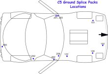
Ground Splice Packs are set as groups
The lower the pack number is would be front of car and larger numbered to rear of car

Splice Pack 100 (with ground tab)

Location: Engine compartment, on top of the right frame rail, just behind the right headlight

Circuits: horn, right headlamp door, underhood lamp, headlamp door control module, fog lamps, A/C compressor clutch, AIR pump, Splice Pack 102.
Note: the stud attaching the ground tab to the frame can get corroded and easily snap off if you are not careful.

Splice Pack 101 (with ground tab)
Location: Engine compartment, on top of the left frame rail, just behind the left headlight

Circuits: brake fluid level switch, washer fluid pump, washer fluid level switch, left headlamp door.
Note: the stud attaching the ground tab to the frame can get corroded and easily snap off if you are not careful

Splice Pack 102 (no ground tab)

Location: taped to the front lamp sub-harness under front bumper, right side. Access requires the removal of 10 7mm body screws holding the bottom of the plastic bumper to the radiator air guide and some under-body trim below the left headlamp.

Circuits: both front marker lamps and both front park/turn signal lamps. Note that this Splice Pack gets its ground from Splice Pack 100.

Splice Pack 122 (no ground tab)
Location: under the battery tray, taped to harness next to firewall.

Circuits: fuel pump relay, oil level switch, Oxygen (O2) sensors.
Note: while you are here, check the harness for abrasion and acid damage. Some cars experienced battery leaks which may have damaged the harness.

Splice Pack 201 (with ground tab) Location: Base of left (driver side) A pillar (by hood release latch), next to Splice Pack 203.

Circuits: Air temperature actuator, data link connector, instrument panel cluster, traction/suspension control switch, driver door module, left door latch, auxiliary power drop connector, wiper motor, steering column lock, left footwell courtesy lamp, hazard switch, telescopic actuator switch.

Splice Pack 202 (with ground tab)
Location: Base of right (passenger side) A pillar.

Circuits: HVAC control module, ignition switch, body control module, Bose relay, glove box lamp, right footwell courtesy lamp, A/T shiftlock control solenoid, blower motor control processor, vanity mirror lamps, inside rearview mirror lamps, blower motor relay, cigarette lighter, passenger door module, passenger door latch.

Splice Pack 203 (no ground tab)
Location: Base of left (driver side) A pillar (by hood release latch). Next to Splice Pack 201.

Circuits: remote CD changer, front door speakers, radio.

Splice Pack 208 (no ground tab)
Location: behind right side of dash, taped to harness above electronics in foot well.

Circuits: Park/neutral switch, Data Link connector, instrument panel cluster, airbag module, Body control module, remote control door lock receiver.

Splice Pack 302 (with ground tab)
Location: in passenger compartment, behind passenger door opening rear trim.

Circuits: Rear compartment (or folding top) lid latch, lid release switch, both rear compartment courtesy lamps, fuel door lock actuator, passenger seat pump and relay center, radio power antenna.

Splice Pack 400 (no ground tab)
Location: taped to rear body harness on right side.
Access requires the removal of the right backup lamp.

Circuits: All rear lamps (tail/stop, turn, marker, license plate, backup, center stop), rear compartment right courtesy lamp.

C5groundsplice.jpg
 

Nickerbocker Glory

CCCUK Member
Very useful thank you. I've sent a query to EFI - looks like they have pretty much everything 'connector' wise. Yes, a good idea to have a separate Techie section....
 
Top