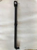
Whilst waiting for the slip yolk to arrive I have been working on a few areas that need to be resolved before the engine can be started and the transmission fitted.
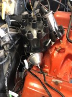
The first of these was the horn relay. The horn relay sits on the drivers side of the engine bay tucked up under the lip for the front wing just in front of the vacuum reservoir. It consists of a relatively simple relay to operate the horn, an electrical distribution stud for the wiring (which is largely unrelated to the horn) and an integrated plastic bracket that is used to mount it to the fibre glass inner wing. A lot of C3 owners are probably now scratching their heads wondering what I am talking about. That's because this arrangement was only used on the '72 and '73 models. Unfortunately that makes these relays rather expensive and a new one, together with it rubber grommet fitting kit, works out at about £100 - which is pretty steep for a relay. The stud is fed power from the starter motor terminals. Bizarrely one of the feeds goes back to the air conditioning system so the cable crosses the engine bay twice to feed something that is only a couple of feet from the starter in the first place.
My relay seems to work ok but the plastic bracket is broken.
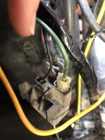
I decided to fabricate a new mounting plate and attach it to the stub of the bracket that remained.... The rubber grommets provide a weatherproof seal for the attachment point.
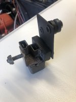
The stud is (I think - will confirm) unfused, unshielded and unswitched ie always live. If this is correct and the relay doesn't work I will be tempted to separate the functions of horn relay and distribution point, put the power stud in some sort of insulated housing and buy a relatively standard 12v relay for the horn. Should find out if it works soon.
Having completed that, the next problem is the transmission shifter hole in the floor. I had bought a new rubber boot and integrated upper reinforcement plate/seal for a manual gearbox and had thought nothing of it. However, my car was originally an automatic and the reinforcement plates (one below the glass fibre floor and one above, riveted together) for an auto shifter are much bigger. Not a lot of people know that.
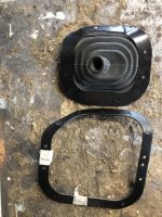
Doing a little bit of research I found that in the US these auto-to-manual conversions are not uncommon and the owners/converters have mostly used a blanking plate to bridge the gap. This is what had been done in my car.....,
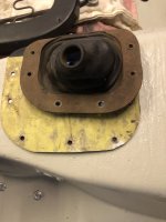
Having (documented in a previous instalment) rebuilt the hole in the floor to the correct size for a manual transmission I then had to make the decision as to whether to build a new bridging plate or buy a new manual-sized reinforcement. New ones are available and relatively cheap but probably taking a month to get to me. Wanting to get a move on (and whilst I had everything open might as well spend a little time on it) I couldn't wait so I took one of the auto sized reinforcement plates and shrank it to a manual size...
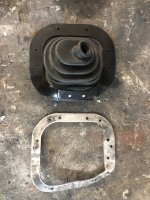
This will now be fitted at the same time as the gearbox to help ensure that I drill the holes for the boot in the floor in the right place so that the gear lever comes through the rubber shroud without putting anything under undue strain.
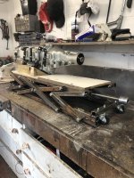
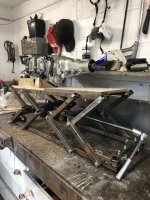
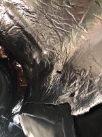
Lastly, I wanted to fit some insulation underneath the floor to minimise heat soak into the cabin and (possibly more importantly) to protect the glass fibre floor from gearbox and exhaust pipe heat. I found some engine bay insulation for a boat that is water and heat resistant, and with the help of a template, cut out a shape of the right size. The insulation is self adhesive and is also secured by the original bent-metal fittings and by the 4 positive battery cable clips. (actually those are not shown here - hadn't refitted the cable at the time the photo was taken). This, together with the wrapped exhaust, will hopefully keep things fairly cool.
Next up: Spend some time checking the engine bay wiring and getting everything electrical labelled, tested and ready for an engine start. Onwards and upwards!


