You are using an out of date browser. It may not display this or other websites correctly.
You should upgrade or use an alternative browser.
You should upgrade or use an alternative browser.
Exciting day - rebuild of 78 coupe
- Thread starter johng
- Start date
Roscobbc
Moderator
In real terms if the vacuum source for the vac advance 'can' is manifold vacuum then it doesn't really matter too much. Soon as you touch the gas pedal the manifold vacuum increases and instantly reduces the degree of vacuum advance to a level the engine is happy with. At idle the vacuum advance will help the engine run cooler, smoother and more efficiently....the 'spark' effectively arriving 'earlier' also gives more time in the combustion cycle for the engine to burn what can be a rich idle mixture more completely.In that case Tim, how do you decide what is the correct amount of vacuum advance?
Most vac/advance units give an extra 15 degrees in addition to centrifugal and static advance.
My own engine has 22 degrees static advance - and 15 degrees centrifugal advance = 37 degrees total. Add-in the 15 degree vacuum and its then a total of 52 degrees.
Most mildly modified SBC's will be happy with 15/16 degrees static advance and 20 degrees centrifugal advance = 35/36 degrees total. Add-in the 15 degree vacuum and its 52 degrees once more. Frightening one might think.....but remember the vacuum advance (which is sourced from under the throttle plates where the vacuum source is at its highest) immediately reduces as soon as the throttle is cracked open.....and will continue to reduce as its opened more........reducing the potential risk of pinking from too much advance.
Forrest Gump
CCCUK regional rep
I might have misled you there John re the vac advance….I was more interested in you adding in more initial and mech timing. My (basic MSD) distributor has adjustable stop cam thing for the vacuum advance. I think I’m set on 14 but the most it will give is 17.I've read that vacuum advance is only of secondary importance, but I find it interesting that Chuffer has 0 degrees, I have 11 degrees and Andy (aka Forrest Gump) told me the other night that hasn't limited his, so he presumably has 20 degrees and yet all of us have cars that tickover and drive well. Mind you we all also have different size engines, compression ratios, inlet manifold, cams, etc. Just goes to show that one size doesn't suit all I suppose.
I have 16 initial and 22 mech = 38 degrees all in at 3000. Vac adds 14 so 52 total. I’m not sure if there is a absolute max recommended total timing, 54 or 56 perhaps. As long as you’re just into the 50s.
I can’t see why you wouldn’t use vac advance on a road car, especially if the vac can is there. Ross explained it well -small benefits perhaps but consider most distributors, even high performance ones like Ross‘s all have the vacuum can.so manufacturers must consider it worthwhile feature
Oneball
CCCUK Member
In that case Tim, how do you decide what is the correct amount of vacuum advance?
No idea. Never played with it, with ign timing the usual rule of thumb is the most you can get without it going bang!
Roscobbc
Moderator
For a race vehicle vac secondary is of zero importance as (theoretically anyway) its being driven (or certainly spec'd-up to) be 'flat out' most of the time. Total timing (for a race car) is obviously of major importance if its going to affect speed and enginme life. I'm guessing that noises like pinking ect will be difficult to hear wearing a helmet and with open exhausts.........On the street in a car with a 'cam' a lack of/slow to operate advance will potentially make the car 'balky' and less responsive at lower operating rpm. As Tim notes "the usual rule of thumb is the most you can get without it going bang!"
Talking about 'old school' pre injected ' Vettes - even stock, totally unmodified engine (if in good order) can benefit from a little bit of ignition advance 'tweaking' - it'll be a bit more responsive, and possibly a littler quicker. The cheapest bit of 'tuning' for years has been this little kit (at about $15)

Moroso 72300 GM HEI Advance Curve Kit
HEI Advance Curve Kit, special design centerplate eliminates over-centering of the centrifugal weights. Designed by Nelson Crozier. Fits: All GM HEI DistributorsFeatures:"Recurve" your distributor for full spark advance at the optimum RPMThree sets of advance springs allow you to adjust the rate of spark advanceWeights and centerplates precision stamped with smooth edges eliminate erratic timingComes with complete installation instructions


Talking about 'old school' pre injected ' Vettes - even stock, totally unmodified engine (if in good order) can benefit from a little bit of ignition advance 'tweaking' - it'll be a bit more responsive, and possibly a littler quicker. The cheapest bit of 'tuning' for years has been this little kit (at about $15)
Moroso 72300 GM HEI Advance Curve Kit
HEI Advance Curve Kit, special design centerplate eliminates over-centering of the centrifugal weights. Designed by Nelson Crozier. Fits: All GM HEI DistributorsFeatures:"Recurve" your distributor for full spark advance at the optimum RPMThree sets of advance springs allow you to adjust the rate of spark advanceWeights and centerplates precision stamped with smooth edges eliminate erratic timingComes with complete installation instructions
johng
CCCUK Member
One of my winter projects is to re-install the aircon system, that I didn't refit when rebuilding the car. I made a start on this over the past few days, with not entirely positive results so far!
First of all I did a pressure test (well a vacuum test to be more precise) on the condenser. As this showed no leaks, I went ahead and gave the fins a good clean out and started to straighten up some that had got rather bent. It was at this point I noticed that one of the tubes which sticks out the side was completely crushed! A good couple of hours wasted and a new condenser is now on the shopping list.
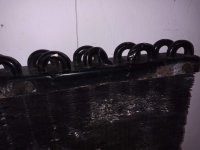
After this disappointment I decided to check out the compressor. The good news was that the clutch works fine. The bad news is that the compressor itself is seized. Another item on the shopping list.
On the positive side both the pressure switch and thermal switch work properly and the liquid line looks fine,
The accumulator/dryer has to be replaced anyway and it seems sensible to replace the 40 year old hoses, so that just left the evaporator. This was not too hard to remove (certainly easier than I had anticipated) and I'm glad that I did take it out. The evaporator fins were extremely clogged and as you can see there was loads of leaves and other debris filling the housing.
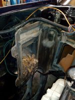
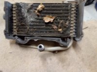
With the evaporator and the leaves removed I can already feel a lot more air coming through the heater vents. Also with the evaporator out of the way I can see that with the heater control set to cold the control flap isn't completely shutting off the air flow to the heater matrix. I'll need to adjust the cable to fix this.
Can't do much more now until I get some bits, which hopefully will find their way into Santa's sack.
First of all I did a pressure test (well a vacuum test to be more precise) on the condenser. As this showed no leaks, I went ahead and gave the fins a good clean out and started to straighten up some that had got rather bent. It was at this point I noticed that one of the tubes which sticks out the side was completely crushed! A good couple of hours wasted and a new condenser is now on the shopping list.

After this disappointment I decided to check out the compressor. The good news was that the clutch works fine. The bad news is that the compressor itself is seized. Another item on the shopping list.
On the positive side both the pressure switch and thermal switch work properly and the liquid line looks fine,
The accumulator/dryer has to be replaced anyway and it seems sensible to replace the 40 year old hoses, so that just left the evaporator. This was not too hard to remove (certainly easier than I had anticipated) and I'm glad that I did take it out. The evaporator fins were extremely clogged and as you can see there was loads of leaves and other debris filling the housing.


With the evaporator and the leaves removed I can already feel a lot more air coming through the heater vents. Also with the evaporator out of the way I can see that with the heater control set to cold the control flap isn't completely shutting off the air flow to the heater matrix. I'll need to adjust the cable to fix this.
Can't do much more now until I get some bits, which hopefully will find their way into Santa's sack.
johng
CCCUK Member
I had my windscreen replaced yesterday (for the second time this year!). The Auto Windscreens guy had no trouble cutting through the glue with his knife and once the screen was out we saw that it hadn't actually been glued along the bottom edge. There is a depression in the panel that the glass is meant to be stuck to and even though the previous fitter had measured where to put the glue on the glass, the glue had ended up just above the depression.
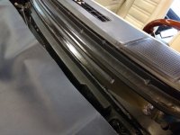
To make sure this didn't happen again, yesterday's fitter put the damming strip and glue on the body instead of the screen. This seemed to work out fine and all is now complete again.

To make sure this didn't happen again, yesterday's fitter put the damming strip and glue on the body instead of the screen. This seemed to work out fine and all is now complete again.
Forrest Gump
CCCUK regional rep
That wasn't very clever calculation to end up with no fixing along the bottom edge. You must have been getting some fresh air ventilation along there - high pressure point base of screen. As a positive, suppose it made old screen removal easier! I fitted the foam tape damming strip to the frame not the screen - seemed obvious to me to align it that way and drop the screen onto it.
johng
CCCUK Member
No there was nothing obvious. It was close to one of the screen clips but wasn't close enough to have touched it. Maybe the lack of glue along the bottom edge allowed the windscreen frame to twist when I hit a pothole or when I jacked it.Could you see any reason for the crack?
johng
CCCUK Member
Yes the screen came out much easier than I was expecting. Also I had the same thing as Oneball, the glue peeled easily off of the frame. The fitter thought this was because the frame hadn't been primed. Apparently some companies say to prime the metal others say not to. This time he did.That wasn't very clever calculation to end up with no fixing along the bottom edge. You must have been getting some fresh air ventilation along there - high pressure point base of screen. As a positive, suppose it made old screen removal easier! I fitted the foam tape damming strip to the frame not the screen - seemed obvious to me to align it that way and drop the screen onto it.
Forrest Gump
CCCUK regional rep
johng
CCCUK Member
Andy, I know that you can get bushed conrods, but is that standard or just to create a fully floating piston?
Oneball
CCCUK Member
Andy, I know that you can get bushed conrods, but is that standard or just to create a fully floating piston?
If there is a bush in the con rod, the gudgeon pin is fixed in the piston usually by means of a circlip or spiral clip and the little end rotates around the pin.
If the con rod is not bushed the gudgeon pin is an interference fit in the little end and the piston rotates around the pin.
The two types of rod and piston aren’t interchangeable.
Most factory SBC and BBC have interference fit gudgeon pins.
Oneball
CCCUK Member
johng
CCCUK Member
Repaired my electric aerial today. There is a solid nylon (or similar material) rod inside which pushes/pulls the aerial up and down.
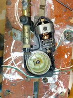
Mine had broken at the top end of the aerial, but if you look closely you can see that it was cracked in several other places as well. No doubt the effect of many years of ageing. As far as I tell, repair kits are no longer available for this, but I managed to get some 2mm bowden cable with a plastic coating that was the same diameter as the nylon rod. I set fire to the nylon at the fixing at each end! This very effectively melted the nylon out of the metal fixings and allowed me to glue the bowden cable back in. At the bottom end I also put on some heat shrink to help hold it together. I didn't do this at the top end as I was worried that this might get jammed inside the aerial tube and stop the aerial coming down. I was also careful to make sure the inner metal of the bowden cable didn't touch the aerial rod, as I expect that would change the aerial length and affect the reception.
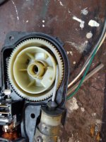
I've run it up and down half a dozen times and it hasn't broken yet

Mine had broken at the top end of the aerial, but if you look closely you can see that it was cracked in several other places as well. No doubt the effect of many years of ageing. As far as I tell, repair kits are no longer available for this, but I managed to get some 2mm bowden cable with a plastic coating that was the same diameter as the nylon rod. I set fire to the nylon at the fixing at each end! This very effectively melted the nylon out of the metal fixings and allowed me to glue the bowden cable back in. At the bottom end I also put on some heat shrink to help hold it together. I didn't do this at the top end as I was worried that this might get jammed inside the aerial tube and stop the aerial coming down. I was also careful to make sure the inner metal of the bowden cable didn't touch the aerial rod, as I expect that would change the aerial length and affect the reception.

I've run it up and down half a dozen times and it hasn't broken yet
johng
CCCUK Member
A couple of fairly large boxes of aircon parts have arrived from Santa, but as it's not yet Christmas I'm forbidden from playing with them  . However, nothing to stop me sorting out the bits I'm going to re-use, so I've given the evaporator a good clean up inside and out and I've made a start on the various brackets, which like the rest of the car were a bit cosmetically challenged.
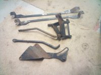
In order to make a bit of space, I got rid of my sandblast cabinet once the major work on the car was done and just kept the mobile blaster that I used on the large bits like the frame. I thought that I'd try to create a temporary cabinet for these few bits to try and contain the sand (well glass beads really). This was my first attempt.
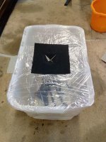
It worked very well at keeping in the sand, trouble was it very quickly became impossible to see what I was doing! Nevertheless, the brackets are all now blasted and painted, I'll post some photos tomorrow.

In order to make a bit of space, I got rid of my sandblast cabinet once the major work on the car was done and just kept the mobile blaster that I used on the large bits like the frame. I thought that I'd try to create a temporary cabinet for these few bits to try and contain the sand (well glass beads really). This was my first attempt.

It worked very well at keeping in the sand, trouble was it very quickly became impossible to see what I was doing! Nevertheless, the brackets are all now blasted and painted, I'll post some photos tomorrow.


